© Copyright 2020 Foshan Membrane Technology Co., Ltd. All rights reserved. Sitemap
The rapid rise of flexible electronics is leading a set of revolutionary technologies, such as wearable electronics, electronic skin, smart clothing, foldable phones, implantable medical devices, and so forth.[1-3] These portable, wearable, and flexible electronic devices raise an apparent demand for integrated flexible power sources. In this respect, new electrochemical energy storage (EES) systems have drawn increasing attentions, due to the high energy density and other performance parameters required, in comparison with conventional physical capacitors.[4] Over the past few years, much progress has been witnessed in the development of high-performance flexible EES devices, including metal-ion batteries, supercapacitors, metal-air batteries, metal-sulfur batteries, and fuel cells.[5-7] Aiming for both high energy and power density, long cycling stability, good mechanical properties, and device safety, many works have been dedicated to exploring suitable and effective electrode/electrolyte materials, as well as optimal structures and device configurations.[8] Among the variety of building blocks for electrode/electrolyte, nanofibers have been demonstrated to be one of the best candidates, owing to their large surface-to-volume ratios, superior mechanical properties (such as stiffness, tensile strength, and flexibility) and versatility in building all types of functional components of EES devices.[9] Nanofibers can be effectively fabricated by spinning techniques, including wet spinning,[10] dry spinning,[11] and in particular, electrospinning. Among them, electrospinning shows the unique advantages, since it has the wide applicability in fiber fabrications for nearly all kinds of materials (organics, inorganics, and hybrids), as well as excellent controllability for dimensions and microstructures of the resultant nanofibers.[12, 13]
In recent years, enormous efforts have been dedicated to utilizing electrospun nanofibers to build high-performance flexible EES devices.[14] The large variety of materials, such as carbon materials, polymers, and inorganic compounds, have been electrospun to nanofibers with intrinsic flexibility, and they have been used to fabricate key flexible EES components, that is, current collector, separator, and electrochemical active materials.[15] Figure 1 shows several typical nanostructured fibers and their applications in supercapacitors, metal-ion batteries, and metal-air batteries. Supercapacitors offer the high power density, superb cycle life, and low maintenance cost, but low energy density. Electrospinning nanofibers can improve their capacities by forming various porous structures and incorporating pseudo-capacitive materials.[16] Although metal-ion batteries exhibit high energy density in theory, achieving a high power density is still an issue for practical applications. Electrospun nanofibers are promising to overcome this bottleneck problem by improving both ion and electron conductivities.
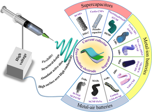
Figure 1
Schematic illustration of nanofiber electrospinning for various materials and advantages of electrospun nanofibers in the applications of flexible electrochemical energy storage devices.
Up to now, several reviews on flexible nanofibers applied in EES devices have been reported.[17] For example, Chen et al.[18] summarized the latest development of fiber supercapacitors in terms of electrode materials, device structure, and performance. In addition, there are a couple of reviews on the fabrication and future challenges of flexible metal-ion batteries and metal-air batteries.[7, 8, 19, 20] However, very few reviews have focused on applications of electrospun fibers in flexible EES devices.
Since the 1990s, one-dimensional nanostructures, such as nanowires, nanorods, nanotubes, nanorings, and nanofibers, have steadily emerged as a large new class of nanomaterials that exhibit unique physicochemical and function properties.[21] Electrospinning process has been developed accordingly in the wave of various spinning techniques. It is a direct and inexpensive method to large-scale produce continuous nanofibers in varying configurations. By applying an electric filed to drops of targeted fluid, the electrospinning apparatus can easily manufacture fibers with controllable diameter from submicrons to nanometers, with the wide variety of materials that include organic polymers (e.g. polyvinyl alcohol (PVA), polyacrylonitrile (PAN), polyvinylidene fluoride (PVDF), and polystyrene (PS)),[22-25] inorganic metal oxides (e.g. CuO, Fe2O3, TiO2 and NiO, NiFe2O4, and LiMn2O4), carbon materials (e.g. graphene, carbon nanotube (CNT), and graphite), and organic/inorganic composites (e.g. PVA/TiO2, Carbon/SnO2, Graphene/TiO2, Nylon-6/gelatin, collagen/hydroxyapatite).[24, 26, 27]
The basic electrospinning setup in a laboratory includes a syringe filled with the material solution, needle tips, and fixed metal collection plates.[28] A positive electrode is connected to the end of the needle, and the metal collector is grounded to the negative electrode. Between the two electrodes, a high electric field of 100–3000 KV m−1 is applied. When the applied electrostatic force on the material solution overcomes the surface tension, nanofibers are ejected from the tip and collected on the stationary plate.[29] In this process, the charge in material fluid interacts with the applied electric field to form the well-known Taylor cone.[30] After the cone is subjected to a strong electric field gradient, the droplet becomes unstable and shoots a jet of fluid from the head of the Taylor cone. The liquid injection process is affected by the coulomb force, external electric field applied, viscoelastic force, surface tension, gravity, and air resistance. Therefore, the beginning of a buckling can be observed. As the electric field forces stretch over a large range and the solvent eventually evaporates, the nanofibers are thus formed and collectable on the target.
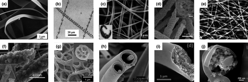
Figure 2
Nanofibers with various structures fabricated by electrospinning technique. a) Flat ribbon structure of 29 wt% Formalin-Aceto-Alcohol-3 nanofibers. Reproduced with permission.[38]Copyright 2019, John Wiley and Sons. b) Helical structure of PEO nanofibers. Reproduced with permission.[27]Copyright 2004, American Institute of Physics. c) Side-by-side PVP/PAN structure of carbon nanofibers. Reproduced with permission.[39]Copyright 2011, Elsevier. d) Bead-like structure of integrating few-layer MoS2carbon nanofibers. Reproduced with permission.[40]Copyright 2020, Elsevier. e) Bamboo structure of PAN/PVP nanofibers with Fe/Co-nitrogen-carbon catalysts. Reproduced with permission.[41]Copyright 2019, John Wiley and Sons. f) Porous hollow structure of WO3nanotube. Reproduced with permission.[42]Copyright 2019, American Chemical Society. g) Multichannel structure of MnO2nanohair decorated carbon nanofibers. Reproduced with permission.[43]Copyright 2015, Royal Society of Chemistry. h) Nanowire-in-microtube structure of TiO2nanofibers. Reproduced with permission.[44]Copyright 2010, American Chemical Society. i) Core-shell structure of V2O5hybrid nanofibers. Reproduced with permission.[45]Copyright 2019, American Chemical Society. j) Multi-layer structure of C-core/Si-medium/C-shell nanofibers. Reproduced with permission.[46]Copyright 2014, Royal Society of Chemistry.
The orientated collection and mass production of electrospun nanofibers are two major challenges for industrialization. To aim for forming more orientated nanofibers, many works have been done to improve the electrospinning jet deposition by optimizing either electrospinning device or fiber precursor. For example, the alignment of the fibers can be achieved by keeping the fiber deposition rate in line with the drum speed, or by magnetizing the polymer solution by adding a magnetic polymer.[47, 48] Large-scale production is challenging, because the quantity and quality of the electrospun fibers cannot be guaranteed simply by using multi-nozzle. And it also brings new problems. For example, dense needles create repulsion and risk unexpected nozzle blockage. So several dedicated companies have developed various needle-free electrospinning techniques to avoid the nozzle blockage issue.[49] If the electrospun nanofibers can be orientated, collected, and produced on a large scale, it will be more attractive for applications in flexible EES devices.
Over the recent years, there has been an impressive progress that is made in the development of key components (current collector, separator, and freestanding electrode active material) for flexible EES devices. The versatile electrospun nanofibers can act as the separator, current collector, and freestanding active materials, which provide effective ways to realize the flexibility of energy storage devices. The composition and morphology of the electrospun fibers have a great influence on the mechanical and electrochemistry performances. Continuous efforts have thus been made to explore suitable electrospun nanofibers for high-performance flexible EES devices. In this section, we will first briefly describe the application of electrospun nanofibers in terms of being employed as the three key components of flexible EES devices. Then, the state-of-the-art electrospun nanofiber-based devices, including supercapacitors, metal-ion batteries, and metal-air batteries, are comprehensively reviewed.
As one of the essential parts of an EES system, the separator is used to ensure that the appropriate ions travel freely between the anode and cathode, while the electrical contact (short circuit) is resisted between any electrodes.[50] High-quality separators are especially crucial for flexible EES devices, since they risk many leakage and short circuit problems when they are subjected to deformations. Commercial polyolefin separators have the poor wettability, small volume porosity, and small pore size, resulting in inferior ionic conductivity. Moreover, polyolefin separators suffer from thermal contraction at elevated temperatures, resulting in risk of internal short circuit.[51] To overcome these issues, electrospun polymer fibers such as PAN, PVA, polyvinyl chloride (PVC), PVDF, and polyethylene oxide (PEO), have been explored as separators that exhibit superior ionic conductivity and reliable flexibility.[52] For example, Dong Zhou designed a cationic polymerized cyanoethyl polyvinyl alcohol (PVA-CN) framework that is embedded in succinonitrile (SN) -based solid electrolyte. The cross-linked PVA-CN polymer framework not only possesses the enhanced mechanical properties but also prevents electrolyte leakage at elevated temperatures. Due to the unique hierarchical structure and structural similarity among the materials, the all-solid-state electrolyte exhibited a high ionic conductivity at room temperature (0.30 S), high lithium-ion migration number (0.57), good mechanical strength (15.31 MPa), outstanding safety, and mechanical flexibility. It is expected to be one of the most promising electrolyte materials for the next generation of lithium-ion battery due to its superior performance and simple manufacturing process.[53] In addition to the organic polymer separators briefly discussed above, electrospun fiber-based inorganic separators were also reported. For example, Jing et al. prepared a nonwoven ZrO2 ceramic separator for lithium-ion battery and achieved excellent electrolyte wettability and ionic conductivity. The ZrO2 separator not only sustains a higher current density than the commercial separator, but also has remarkable mechanical flexibility and flame-resistance.[54]
The current collector in an EES device serves as the structural support for electrode materials and builds the electronic transmission bridge between the electrode material and the external circuit. Considering the targeted application of EES in wearable electronics, the current collector is desired to have omni-directional flexibility, such as the capability of bending, twisting, and stretching.[63] Additionally, the current collector should have a lightweight but robust mechanical property to prevent structural damage during deformation, and the current collector is also expected to bind the electrode materials strongly to keep them from peeling off.[64] Conventional current collectors of metal foils or foams are apparently heavy and not sufficiently flexible. Moreover, the relatively smooth surface of metal current collector results in a weak adhesion for electrode active materials, which casts a shadow over the flexibility of EES device. To cope with these problems, conductive electrospun nanofiber-based current collectors have numerous advantages. Firstly, a network formed by interweaved electrospun nanofibers possesses good mechanical property, owing to the intrinsic flexibility of the one-dimensional fibers. Secondly, the electrospun nanofibers can form in a hierarchical porous structure that provides large surface area for supporting of electrode active materials. As a result, the weight ratio of the current collector in an electrode can be significantly reduced. Thirdly, the rough surfaces of electrospun nanofibers are favorable for strong binding of active materials, especiallywhen the active materials are chemically grown on the fibers. The strong binding between the fiber-based current collector and active materials contributes to a reliable deformation stability for a flexible EES device.
Several materials have been explored in recent years for the preparation of fiber current collectors, including metal or plastic fiber,[65] ultrafine metal fiber,[66] conductive polymer fiber,[67] and carbon nanofiber.[68] Metal fibers are characterized by a high electronic conductivity, but their weight was hard to ignore, and the shape memory effect of metal fiber also limits its flexibility.[66] Metal-coated plastic fibers have shown a quite good combination of conductivity and flexibility.[65, 69, 70] In terms of the availability, conductive polymer and carbon nanofibers are more competitive candidates of flexible current collectors, because they can be prepared in facile methods and they feature of lightweight, intrinsic conductivity and flexibility.[71, 72]
Although the electrospun fiber-based current collector presents great advantages for flexible EES, the utilization of a separate current collector inevitably introduces extra weight to the EES electrode and generates fragile electronic interface between the current collector and active material. An ideal flexible electrode is expected to be a freestanding and network that homogeneously integrates electronic conductive units and electrochemical active sites.[73, 74] This can be realized by electrospinning a single-phase material that has both high conductivity and electrochemical activity, or a homogeneous mixture of conductive and active agents.
The material flexibility of electrospinning technique makes it quite advantageous for building freestanding electrodes. A single-phase material nanofiber functionalized with both high conductivity and electrochemical activity through strategies of elemental doping and crystal-structural engineering.
Supercapacitors are among the ideal power sources for wearable electronics because of their fast charge/discharge rates, superb power density, and reversible electrochemical characteristics. Nevertheless, supercapacitors suffer from the low energy density, which limits their application. Nanomaterials with various dimensional structures have been developed for high-performance supercapacitors.[18] In particular, one-dimensional nanofibers for flexible electrodes have attracted more attentions due to their inherent advantages, such as a large specific surface area, hierarchical porous structure, good flexibility, and mechanical reliability.[16] In this section, we will present an overview of the fabrication of various types of electrospun nanofibers and their applications as electrode materials for supercapacitors, including both chemical double-layer capacitors (EDLCs) and pseudo-capacitors.
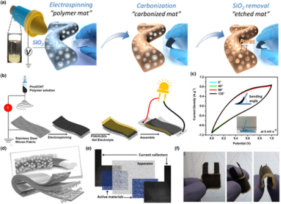
Figure 3
Application of electrospun fiber in electrical double-layer capacitors and pseudo-capacitors. a) Schematic illustration of fabrication process of N-enriched carbon fibers mat. Reproduced with permission.[88]Copyright 2016, Elsevier. b) Schematic illustration of fabrication process of a full symmetrical all-solid-state flexible supercapacitor with Pind/CNT nanofibers as electrode active materials. c) The CV cures at scan rate of 5 mV s−1under various bending angles. The inset shows the employed equipment. Reproduced with permission.[99]Copyright 2017, Elsevier. d) Schematic demonstration of a symmetrical full-supercapacitor with ZnO/PEDOT:PSS/P(VDF-TrFE) nanofibers as electrode materials. Reproduced with permission.[100]Copyright 2017, John Wiley and Sons. e) Schematic representation of the stack-layered textile supercapacitor. f) Photograph of a 3 cm2all-textile flexible supercapacitor. Reproduced with permission.[101]Copyright 2011, Elsevier.
Conductive polymers such as polyindole (Pind), Poly(3,4-ethylenedioxythiophene) (PEDOT), polyaniline (PANI), and their derivatives are another class of electrode materials for pseudo-capacitors.[67] Using the electrospun Pind/CNT Composites as the active material and a flexible stainless-steel woven fabric as the current collector, Tebyetekerwa et al. prepared a sandwich type symmetrical supercapacitor (as shown in Figure 3b). In the simulation of the real scene at the bending positions of 40°, 90°, and 135° angles, there was no significant change in the supercapacitor CV test (Figure 3c), indicating an excellent device flexibility.[99] Sami et al. successfully fabricated PEDOT:PSS-coated conductive polyvinylidene fluoride-tetrafluoroethylene (P(VDF-TrFE)) nanofibers with ZnO nanorod arrays decorated on surface. This nanofiber composite was used in highly flexible, lightweight, and all-solid-state supercapacitors (Figure 3d). The areal capacitance of the symmetrical supercapacitor reached 1.22 mF cm−2, which was very promising for the next generation of integrated fully flexible EES.[100] The fabrication of all-textile flexible supercapacitors by facile electrospinning technology has been also been investigated. For example, the all-textile supercapacitor prepared by Alexis Laforgue was composed of stacking layers of textile materials. As shown in Figure3e, electrospun PEDOT nanofibers and PAN nanofibers were used as the electrode active materials and separator, respectively. Carbon cloths were chosen as the current collectors. By assembling these components together with a solid-state electrolyte, a flexible supercapacitor was obtained, which could be arbitrarily bent without delamination of any layers (Figure 3f).[101]
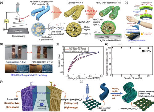
Application of electrospun fiber in stretchable electrochromic capacitors and hybrid capacitors. a) Schematic illustration of fabrication process of PEDOT:PSS-coated WO3nanotube that is supported by Ag nanowire-embedded PDMS substrate. b) Schematic illustration of an all-TSES wearable patch device. c) Real image and demonstration of bleached and colored state of an all-TSES wearable patch device. d) Cyclic voltammetry result of 20% stretch imposed on all-TSES device. e) Normalized capacitances of the all-TESE wearable patch device under different tensile strains. Reproduced with permission.[42]Copyright 2019, American Chemical Society. f) Schematic illustration of a quasi-solid-state sodium-ion hybrid capacitor containing the CNF@NVPF cathode and the PCNF anode. g) Schematic illustration of fabrication process of aligned arrays of NVPF on carbon nanofiber. Reproduced with permission.[102]Copyright 2019, John Wiley and Sons.
In traditional EES devices, there is always a tradeoff between the energy density and power density, where the two parameters are hard to be improved at the same time. This problem has been tackled by designing the hybrid-type energy storage devices (HESDs), which combine the rapid charge-discharge performance of supercapacitors and the large-capacity performance of the faradaic batteries. For example, sodium ion hybrid capacitors were constructed by using sodium-vanadium fluorophosphate (NVPF) arrays as the intercalative battery cathode, porous carbon nanofiber (CNF) as the capacitive supercapacitor anode, and P(VDF-HFP) as the polymer electrolyte, as shown in Figure 4f.
Metal-ion batteries, such as lithium-, sodium-, potassium-, and zinc-ion batteries, follow the “rocking chair” working principle, where metal ions migrate between the anode and cathode during the charge/discharge process. Unlike supercapacitors, deintercalation-intercalation of metal ions in electrodes calls for materials with specific microstructures. Structurally controllable electrospun nanofibers are bound to be among favorable candidates for flexible electrode materials for metal-ion batteries.
Lithium-ion batteries have been among the best known and the most commercialized for the two decades. An optimal lithium-ion battery electrode material must meet the following criteria: 1) a good electric conductivity to facilitate the charge transfer; 2) a desired structure for multiple lithium-ion insertion and de-insertion in a short diffusion pathway; and 3) small volume changes during charging and discharging. The unique one-dimensional nanostructure of electrospun fiber-based lithium-ion electrode materials is advantageous to satisfy those criteria. For example, Kalluri et al. had compared the electrochemical performance of Li1+x(Mn1/3Ni1/3Fe1/3)O2 nanoparticles and nanofibers. It was found that the self-aggregation behavior of nanoparticles resulted in poor electrochemical performance during cycling process, because of the blocked ion diffusion pathways. Nanofibers possessed self-polymerization resistance and exhibited an improved initial reversible capacity (~109 mAh g−1) and cyclic stability at the 0.1 C rate.[104] Similarly, LiCoO2 and LiMn2O4 electrospun nanofibers composed of ultrafine nanoparticles have also shown to exhibit excellent cycling stability.[105] For example, electrospun LiMn2O4 hollow nanofibers retained 87% of initial reversible capacity after 1250 cycles at the 1 C rate, which was one of the best results obtained for this compound.[106] As a low-cost anode material, TiO2 suffers from its intrinsic insufficient conductivity. By thermal treatment in NH3 atmosphere, Han and co-workers had generated a highly conductive TiN/TiO2-xNy surface layer on the electrospun TiO2 nanofiber. In this way, they were able to improve the rate capability of TiO2 by more than two times.
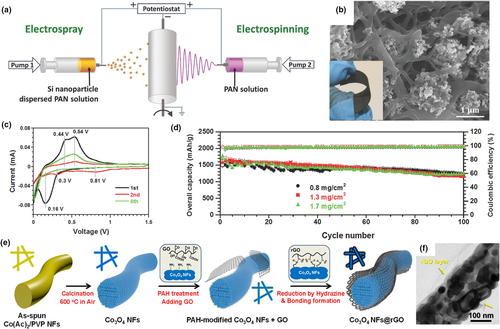
Figure 5
Application of electrospun fiber in lithium ion batteries. a) Schematic illustration of the synthesis process and the architecture of the flexible 3D Si/C fiber paper electrode b) SEM images (top view) of the 3D Si/C fiber paper electrode. The inset displays the electrospun/sprayed flexible paper electrode after carbonization with 72 wt% Si. c) Electrochemical performance:charge/discharge profiles of the flexible 3D Si/C fiber paper electrode in the first five cycles. d) Cycling stability and Coulombic efficiency of the flexible 3D Si/C fiber paper electrodes with different overall loading masses of 0.8 mg cm−2, 1.3 mg cm−2, and 1.7 mg cm−2. Reproduced with permission.[110]Copyright 2014, John Wiley and Sons. e) Schematic illustration of synthesis for the Co3O4NFs and the Co3O4NFs@rGO. f) HRTEM images of the Co3O4NFs@rGO. Reproduced with permission.[111]Copyright 2017, Nature.
As one of the alternative candidates for the widely studied lithium-ion batteries, sodium-ion batteries are more promising for large-scale applications due to the natural abundance and much lower cost of sodium. Compared with lithium ion, sodium ion needs more space for motion intercalation, because of its larger radius. Theoretical calculation shows that 0.37 nm is the minimum layer separation for sodium-ion movement.[112] As a result, sodium-ion host material suffers from volume change more than lithium-ion host. For example, traditional electrode materials, such as carbon-based materials and group IVA and VA elements (e.g., Sn, Sb, and P), transition metal oxides have inferior rate capabilities because of insufficient conductivity and poor cycling stability due to volume expansion caused by sodium-ion insertion.[113] To solve these issues and realize flexible sodium ion-based energy storage devices, researchers have electrospun many types of flexible nanofibers with active materials that either incorporate heteroatom dopants for improved electronic structure, or form in rich porous and composite structures for fast sodium-ion diffusion and reliable cycling stability.[114, 115] For example, the conductivity of carbon nanofibers can be improved by nitrogen doping, due to the delocalized conjugation, formed by the single electron pairs from the nitrogen elements.[117] Furthermore, heteroatom dopants (N, P, and S) in carbon nanofibers can result in vacancies or defects, which can further enhance adsorption of sodium ions. Some of these doping strategies have been demonstrated to effectively enhance the sodium-ion storage performance of carbon nanofibers.[118, 119] Besides, a porous structure can facilitate the diffusion of sodium ion. For example, by using Pluronic F127 as a soft template, Li et al. had electrospun porous carbon nanofibers that exhibited a stable capacity of 140 mAh g−1 during 1000 charge/discharge cycles.[122] The same doping effect also works for transition metal oxide materials. Wu et al. reported the N-doped ordered mesoporous anatase TiO2 (N-MTO) nanofibers showed significantly improved rate performance and cycling stability.[123] This had been attributed to the increased conductivity induced by N-doping and a shortened sodium-ion diffusion length enabled by the ordered porous structure.[123]
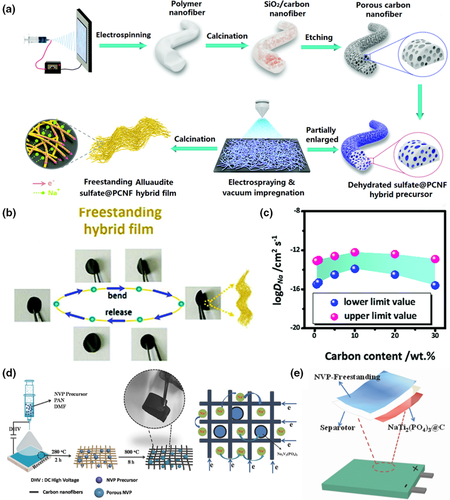
Figure 6
Application of electrospun fiber in sodium ion batteries. a) Schematic illustration of the synthetic approach of alluaudite Na2+2xM2-x(SO4)3sulfate@porous carbon nanofiber (PCNF) hybrid film. b) Flexibility and bending tests of the hybrid film. c) The range of the sodium intercalation coefficients for the hybrid nanofiber electrodes with different carbon content. Reproduced with permission.[127]Copyright 2016, Royal Society of Chemistry. d) Schematic illustration of the preparation procedures of NVP-freestanding composite. e) Inside structure of the flexible sodium-ion soft-package battery. Reproduced with permission.[128]Copyright 2018, John Wiley and Sons.
Potassium ion is another earth-abundant resource and has relatively low reduction potential (~2.936 V vs RHE), benefiting from the lowest potential of potassium-ion/potassium redox couple in several organic electrolytes.[129] A significant advantage of potassium ion, over lithium and sodium ion, is that the Lewis acidity of potassium ion is much weaker and solvated potassium ions are smaller than those of lithium and sodium ones. But the desolvated potassium ion that intercalates in electrode lattice is obviously larger than sodium ion and lithium ion, resulting in more risks of large volume change. One-dimensional electrospun carbon-based nanofibers are among the ideal material candidates for long-life potassium ion batteries. In order to solve the huge potassium-ion intercalation issues, Adams et al. treated pre-prepared carbon nanofibers by plasma oxidation. The surface storage of potassium ion was increased by oxygen functionalities after plasma oxidation treatment. Their in-situ characterization showed that the one-dimensional structure had cyclic stability and rate capability, despite that the inter-lattice spacing(002) of graphitic expanded from 0.37 to 0.46 nm.[130] At the same time, Zhang et al.[131] had combined N-doped hollow carbon nanofibers with tapered rod-shaped nanomaterial NiCo2S4 (Figure 7a). Since the pseudo-capacitance behavior enhances the electrochemical rate performance, it is significant to distinguish the surface control capacity (i.e., the pseudo-capacitive capacity) and the diffusion control capacity in the redox process at different scanning speeds for potassium-ion batteries. The voltage profile of a typical pseudo-capacitance current (blue region) relative to the total current is shown in the Figure 7b, and the contribution of the pseudo-capacitance is 56.1% at a scan rate of 0.7 mV s−1. The contribution of pseudo-capacitance increases with the increase in scanning rate from 0.1 to 0.9 mV s−1 (Figure 7c). Obviously, it could be attributed to the fact that the hollow carbon tube and tapering array structure provided a large potassium-ion contact surface, which made enhancement in redox pseudo-capacitance and rate performance. The 3D structured composites also showed excellent mechanical properties, implying the potential for application as an anode for flexible potassium-ion batteries. Yi et al.[132] fabricated the N, P co-doped carbon nanofibers decorated with MoP ultrafine nanoparticles (MoP@NPCNFs), as shown in Figure 7d. The as-synthesized hybrid nanofibers could be assembled to flexible membrane, and their porous 3D structure not only increased the contact area with electrolyte, but also shortened the transport distance of ions. Because of the advantages offered by the 3D structure, the composite nanofibers showed excellent rate capabilities. It can be seen from the Figure 7e that the electrode could maintain a high reversible capacity of 223 mAh g−1 even at the extremely high current density of 2 A g−1. Xu et al.[133] electrospun MC-CFs through adding PMMA in PAN precursor solution, where amorphous MC-CFs possessed a unique multichannel structure with a large number of meso and micro pores, which could promote electrolyte penetration, buffer volume changes. The microstructure of MC-CFs was regulated by tuning PMMA ratio in the precursor solution. MC-CFs with optimized microstructure achieved a capacity of 110.9 mAh g−1 after 2000 cycles at a higher current density of 2000 mA g−1 and a high reversible capacity of 420.1 mAh g−1 at current density of 50 mA g−1. To alleviate the reliance on the fossil resources, Li et al. electrospun carbon nanofiber nonwoven fabric by using a mixture of coal liquefaction residue/PAN/preasphaltene as the precursor. The resulted nanofibers exhibited an outstanding cycling performance for potassium-ion battery, with a capacity retention of 98% after 320 cycles.[134]
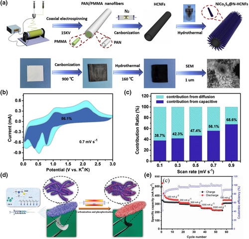
Figure 7
Application of electrospun fiber in potassium ion batteries. a) Schematic illustration of the preparation process of NiCo2S4@N-HCNFs. b) CV curves of NiCo2S4@N-HCNFs with the pseudo-capacitive fraction shown by the shaded regions at a scan rate of 0.7 mV s−1. c) The capacitive contribution ratios of the NiCo2S4@N-HCNFs electrode at different scan rates from 0.1 to 0.9 mV s−1. Reproduced with permission.[131]Copyright 2020, Elsevier. d) Schematic illustration of the synthesis procedure of the flexible and freestanding MoP@NPCNFs membrane. e) Rate performance of the flexible and freestanding MoP@NPCNFs composite membrane with rates ranging from 100 to 2000 mA g−1. Reproduced with permission.[132]Copyright 2019, John Wiley and Sons.
As an ideal power source for aqueous energy storage system, Zn-ion batteries have been paid wide attention more recently, due to their high safety, low cost, and environmental friendliness.[135, 136] However, the low energy density and low mass loading are among the parameters limiting their practical applications. Wang et al. fabricated a class of the core-shell hierarchical structured hybrid fibers with encapsulated metal oxide nanoparticles for flexible Zn-ion batteries.[45] As illustrated in Figure 8a, the hierarchical structure could provide a dual electron-conducting system and a highly porous network for ion diffusion. Two kinds of metal oxides, that is, Zn2V2O7 and V2O5, were embedded in the hybrid fiber, respectively, and they achieved capacities of 162 mAh g−1 and 409 mAh g−1, respectively, at a high current density of 8 A g−1. Bending deformation from 0° to 720° had no significant effect on them (Figure 8b). With the flexible battery constantly bending and loosening, the shape of the CV curve could still be well maintained. The well-kept redox peaks were detected at high bending (720°) during cycling. Moreover, after a series of cutting or drilling treatments, the batteries could remain the well-defined charge and discharge characteristics (Figure 8c,d). These results demonstrated that electrospun fiber could endow high reliability and stability for flexible Zn-ion batteries. Flexible Zn-ion batteries that possess good cycling stability even in severe environments are very promising for application in wearable electronics.
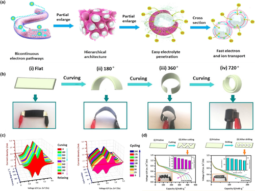
Figure 8
Application of electrospun fiber in zinc-ion batteries. a) Schematic illustration of the hierarchical structure for the hybrid fiber, the bicontinuous conductive pathways, easy electrolyte penetration, and facile electron/ion transport pathways. b) Schematic illustration and digital photographs of the flexible battery at different curving states. c) The CV curves of the battery with the V2O5-based hybrid fibers at different curving states and the battery with the Zn2V2O7-based hybrid fibers under curving of 720°. d) The discharge curves of the flexible batteries with hybrid fibers based on V2O5and Zn2V2O7under cutting or drilling tests. Reproduced with permission.[45]Copyright 2019, American Chemical Society.
Flexible metal-air batteries exhibit much higher theoretical energy densities than those of metal-ion and lead-acid batteries and can be excellent candidates of durable power source for wearable electronics. In the common configuration of a flexible metal-air battery, a flexible anode can be easily fabricated by using a thin metal foil or metallic powder coated on a flexible substrate. However, the fabrication of an efficient flexible air cathode is non-trial, because the cathode is required to uptake oxygen from the surrounding environment to participate in the reaction. It has been a research hotspot to develop highly stable, low cost, and flexible air cathodes with excellent catalytic functionality.
Zn-air batteries are among the most attractive metal-air batteries, because of their low cost, good rechargeability, and high safety. Recently, many research works have been carried out to develop nanofiber-based flexible air electrodes with high efficiencies of ORR and OER. Among them, carbon-based nanomaterials are considered as the valuable substitutes for precious metal-based OER/ORR catalysts. Heteroatom-doping, like N, S doping, in carbon is a common approach to enhance catalytic properties, where the different atomic size and electronegativity sufficiently alter the electron configuration and charge distribution around the active site.Metal-organic framework (MOF)-derived carbon-based materials have aroused great interests more recently for their unique catalytic active metal centers and tunable hierarchical porous structures. Wu et al. synthesized porous carbon nanofibers doped with iron by using Zn,Fe-zeolitic imidazolate framework (ZIF) as the precursor. The obtained nanofibers exhibited the desired hierarchical porosity, conductive honeycomb network, and highly active Fe-Nx-C centers. The Zn-air battery made of the Fe/C nanofibers exhibited a current density of 90 mA cm−2 and a peak energy density of 61 mW cm−2.[143] Zhang et al. fabricated MOFs-derived Co/N-doped porous carbon fibers by the electrospinning-assisted assembly of bimetallic zeolitic imidazolate framework nanoparticles. The specimens prepared with the molar ratio of Zn:Co is 5:1 showed rapid mass transport properties and the resulted ORR performance was comparable to that of Pt/C catalyst, while the material cost was much lower than the noble metal.[144]
It is important to properly integrate the flexible electrospun fiber-based air cathodes to full flexible Zn-air batteries. In this aspect, pioneer works have been done using carbon nanofiber-based materials. Pan et al. successfully obtained flexible CuCo2S4 nanosheets@N-doped carbon nanofibers (CuCo2S4 NSs@N-CNFs) by electrospinning combined with in situ sulfurization at room temperature.[145] As shown in Figure 9a, the flexible Zn-air battery was assembled by using the CuCo2S4 NSs@N-CNFs as the air cathode and zinc nanosheets@carbon nanotubes film as the anode. This battery was demonstrated to exhibit unchanged charge-discharge curves when it was bended from 0° to 180°, showing an extraordinary flexibility (Figure 9b).
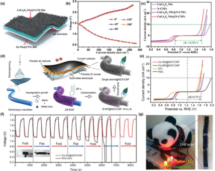
Figure 9
Application of electrospun fiber in zinc-air batteries. a) Schematic diagram illustration of the CuCo2S4NSs@N-CNF-based flexible quasi-solid-state zinc-air battery. b) Discharge-charge polarization curves of the as-fabricated flexible zinc-air battery under different bending angles. c) ORR and OER polarization curves of CuCo2S4NSs, N-CNFs, CuCo2S4NPs@N-CNFs, and CuCo2S4NSs@N-CNFs. Reproduced with permission.[145]Copyright 2019, John Wiley and Sons. d) Schematic illustration of the “impregnation-carbonization-acidification” process for scalable fabrication of M SA@N-CF/CNF film as flexible air cathode in a wearable zinc-ion battery. e) ORR/OER bifunctional LSV curves of Co-SA@N-CF/CNF, Co NP@N-CF/CNF, Ir/C, and Pt/C. f) The charge-discharge curves of the wearable zinc-air battery under alternately folding and releasing conditions. g) Digital photograph shows three wearable zinc-air batteries in series as a scarf lighting up different light-emitting diodes synchronously. Reproduced with permission.[146]Copyright 2019, John Wiley and Sons.
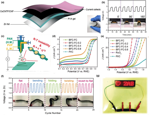
Figure 10
Application of electrospun fiber in zinc-air batteries. a) Schematic representation of an all-solid-state flexible zinc-air battery. b) Galvanostatic discharge-charge cycling curves of CoNCNTF/CNF film-based zinc-air battery with bending strain applied every 30 min. Reproduced with permission.[147]Copyright 2018, Elsevier. c) Schematic illustration of the synthesis of 1D BFCs. d) ORR and e) OER activity of catalysts tested in the 0.1 M KOH electrolyte. f) Cycling profiles of ZAB-BFC-FC-0.2 under the current density of at 2 mA cm−2upon various mechanical deformations. g) Digital photograph of a LED panel powered by three ZAB-BFC-FC-0.2 connected in series at −20°C. Reproduced with permission.[41]Copyright 2020, John Wiley and Sons.
The semi-open structures for the zinc-air batteries pose severe challenge for operation at low temperature. Pei et al.[41] proposed a flexible Zn-air battery with low temperature adaptability, based on a bamboo-like fibrous catalyst and hydrogel electrolyte with a polarized terminal group. As shown in Figure 10c, they used coaxial electrospinning to place PAN and PVP on external and internal flows, respectively, while controlling different feeding rates of PVP (0.2/0.4/0.8 mL h−1). The bamboo-shaped fibrous catalysts formed at the inner solution flow rate of 0.2 mL h−1 (denotated as BFC-FC-0.2) delivered the best ORR and OER performance among all tested counterparts (Figure 10d,e). More interestingly for practical applications, the flexible Zn-air battery assembled using the BFC-FC-0.2 air cathode, a zinc foil anode and the alkalified hydrogel (A-PAA) displays a stable charge and discharge profile when undergoing severe deformation (Figure 10f). Due to the outstanding anti-freeze performance of the A-PAA hydrogel, the flexible Zn-air battery could work reliably in a cold environment of −20°C (Figure 10g), which would be of considerable value for the new generation of low temperature tolerant, flexible electronic devices.
Compared with alkaline-based Zn-air batteries, neutral electrolyte-based Mg-air batteries are more compatible for the human body and biomedical applications. Moreover, the magnesium element shows good biological absorption and magnesium ion is harmless to human body. Inspired by the fiber bundle structure of bufo bacteria, Cheng et al. prepared open-mesoporous carbon nanofibers loaded with atomic Fe-Nx (OM-NCNF-FeNx) as an oxygen electrode for Mg-air battery (Figure 11a). The obtained nanofibers were endowed with the following advantages: 3D porous channels improved the mass transport performance, and the interconnected structures increased air diffusion paths, and coupled atomic Fe-Nx sites improved the ORR activity. Accordingly, the OM-NCNF-FeNx electrode-based Mg-air battery delivered better electrochemical performance than that of Pt/C air electrode-based battery.[148] They also constructed a solid Mg-air microbattery using OM-NCNF-FeNx as the air cathode to demonstrate the potential application in flexible/wearable microelectronics devices. The flexibility of the battery was tested and the discharge curve showed no significant change when the battery was bent back and forth, as depicted in Figure 11b. The OM-NCNF-FeNx-equipped battery worked efficiently in a neutral electrolyte with stable discharge voltage plateaus and good flexibility. The research not only demonstrated a potential flexible and bio adaptable power supplier, but also provided a new path for production of carbon nanofibers.
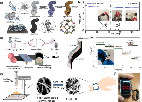
Figure 11
Application of electrospun fiber in Mg- and Al-air batteries. a) Schematic illustration of the open-mesoporous CNFs with the fibrous string structures.b) Discharge curves at 0.05 mA cm−2for the solid-state Mg-air microbattery with OM-NCNF-FeNx, bending strain applied every 30-40 min. Reproduced with permission.[148]Copyright 2018, John Wiley and Sons. c) Schematic illustration of the fabrication of Al-air cathodes by directly electrospinning. d) Rate discharge profiles of Al-air batteries at different bending angles. Reproduced with permission.[149]Copyright 2020, Institute of Physics. e) Schematic illustration of the fabrication process of Fe3C@N-CFs. f) Digital images of LED watch powdered by solid-state Al−air battery (with Fe3C@N-CF air cathode) that are used as the watchband. Reproduced with permission.[150]Copyright 2018, American Chemical Society.
The anode in a common Al-air battery is known to corrode easily in an alkaline solution. Hydrogen evolution corrosion during discharge limits the output voltage and metal utilization. Zuo et al. reported that the corrosion of aluminum anode could be inhibited by surface modification of electrospinning Al2O3 interlayer, where the Al2O3 has been shown to be an effective inhibitor of hydrogen generation. The results showed that the anode with a 4 µm Al2O3 interlayer was more suitable for the micro-equipment with small current discharge, and the capacity could reach 1255 mAh g−1 at 5 mA cm−2.[152]
Though tremendous progress has been made in development of electrospun nanofiber-based air cathodes that drive high efficiency oxygen-related electrochemical reactions, a big issue that hugely impacts the metal-air battery performances is that nitrogen and carbon dioxide in the air can also take part in the cathodic reactions during the battery operation.[153, 154] Compared with the traditional powder catalysts, the nanofiber-based electrocatalysts have the following advantages. First, the electrospun nanofibers form a continuous conductive network for supporting of active material and can achieve superior ion and electron transport properties. Second, for the electrospun nanofiber-based cathodes, the optimization of activity/selectivity can be realized by regulating the surface structure (micro-nano structure, porous structure) and electronic structure (alloys, defects) of the active materials. Third, to meet the needs of flexible wearable energy storage devices, it is necessary to develop electrode materials with good mechanical properties and electrochemical stability. Ultra-thin nanosheet- and nanowire-based electrospun nanofibers can achieve excellent flexibility and mechanical stability.
The rapidly growing interests in both scientific research and huge technology value of consumer markets have led to the timely development of flexible EES devices in the past decade. In this overview, we have examined the fabrication of electrospun nanofibers with a variety of tunable compositions, rich micro-/meso-/nanostructures and desired electrochemical and mechanical properties, and have discussed the latest advances in the performances of these electrospun nanofibers in flexible EES devices. Despite of steady progress, the long-awaited practical application of electrospinning technology in flexible EES devices is still at the initial stage. Ahead of the expected applications at large scales, there are a number of challenges that are still faced with and shall be addressed:
1. With the steady continuation in tuning and evaluation of the electrospun fibrous nanostructures in the coming few years, great efforts shall be made in achieving the rational design, precision synthesis and fine-adjustment of the structure at varying scales down to atomic levels. For their uses as the EES electrodes, one of the essential requirements is a high loading mass of the active materials, in order to enable a high enough energy density and better overall performance. However, an overloading of the active material would reduce the mechanical flexibility of the nanofibers. One of the challenges in the future work is on the delicate balance between achieving a high energy density and at same time maintaining the flexibility of the nanofibers, and the devices thus made of.
2. Although electrospun fibers have widely been used as the cathode, anode, and separator, respectively, there is apparent lack of the fully flexible batteries with all parts assembled by electrospun nanofibers. With few exceptions, most of the EES prototypes made in the previous works are without proper packaging, which limits the overall device performance, reliability, and even essential security. Moreover, the currently on-going exploration of flexible device configurations (including for example the sandwich and cable configurations) is far from be optimized. In addition, most of the mechanical and flexibility properties are tested by simple bending/deformation without proper quantitative analysis. Therefore, it would be necessary to establish a widely acceptable criterion (such as the deformation type and device size) that conforms to the actual flexible, integrated devices, rather than a simple, single configuration. The full potential can only be realized if in-depth analysis is carried out in combination with thorough mechanical studies for both electrospun nanofibers and the thus-made devices.
3. 3D printing technology has enabled precise manufacturing of object with customized structures, so 3D printing has great potential in improving the mechanical properties of flexible EES devices. Electrospun fibers can be either used as fillers in extruded 3D printing or incorporated in 3D printed frameworks. For example, by collecting electrospun fibers on a 3D printed pre-stressed or stretched substrate, highly stretchable fibrous membranes can be formed. The combination of electrospinning and 3D printing techniques is very promising for fabrication of multi-dimensional materials with plentiful micro/macro structures.
4. Currently, there are both great opportunities and challenges for the commercialization and industrial production of electrospun nanofibers. Although electrospinning has been progressing steadily in recent years, it is always a challenge when one moves to the relatively large-scale production. Most of the previous studies on electrospun nanofibers and flexible EES devices are based on the laboratory scale. To achieve an industrial-scale production, the overall cost, power consumption, and environmental impacts must be addressed. Essentially, it would be necessary to reduce the production cost while improving the overall performance and service life. For example, employment of multi-spinneret or needle-free electrospinning is apparently handicapped by their high costs for industry. Therefore, raising the yield and reducing the one-time production cost will help accelerate the lab-to-commercialization transformation.
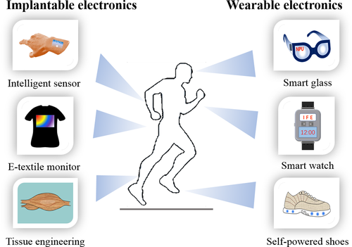
Figure 12
Potential applications of flexible electrospun nanofibers for implanted and wearable electronics.
Article Source:https://onlinelibrary.wiley.com/doi/10.1002/eem2.12146