© Copyright 2020 Foshan Membrane Technology Co., Ltd. All rights reserved. Sitemap
Nanofibers provide dramatic increases in filtration efficiency at relatively small (and in some casesimmeasurable) decreases in permeability. In many laboratory tests and actualoperating environments, nanofiber filter media also demonstrate improved filter life and more contaminant holding capacity. Nanofiber filter media have enablednew levels of filtration performance in several diverse applications with abroad range of environments and contaminants. The performance of nanofibermedia in a mining vehicle cabin air filter will be discussed.
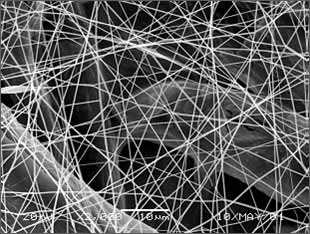
Figure 1. Ultra-WebNanofiber Filter Media
Small fibers in the submicron range, incomparison with larger ones, are well known to provide better filter efficiencyat the same pressure drop in the interception and inertial impaction regimes.W.C. Hinds shows such effect by assuming non-slip flow at fiber surface.
While smaller fiber sizeleads to higher pressure drop, interception and inertial impaction efficiencieswill increase faster, more than compensating for the pressure drop increase.Thus, in the particle size of interest, i.e., from submicron and up, betterfilter efficiency can be achieved at the same pressure drop, or conversely, thesame filter efficiency at lower pressure drop can be achieved with smallerfiber sizes.
Fornanometer-scale fibers, a second factor has to be taken into account: theeffect of slip flow at the fiber surface. Filtration theory generally relies onan assumption of continuous flow around the fiber, with a no-slip condition atthe fiber surface. The theory starts to become less valid when the scale of thefiber becomes small enough that the molecular movements of the air moleculesare significant in relation to the size of the fibers and the flow field. Usinga slip-flow model at the fiber surface can extend the useful range ofcontinuous flow theory. The Knudsen number is used to describe the importanceof the molecular movements of air molecules at the fiber surface to the overallflow field. The Knudsen number can be written as
Whereλ is the gas mean free path (the dimension of the non-continuous nature ofthe molecules), and rf is the radius of the fiber. When Kn becomesnon-neglible, the continuous flow theory, which does not take into account themolecular nature of air, starts to become less valid. While there is no exactKn above which slip flow will prevail, it generally needs to be considered whenKn > 0.1, and definitely needs to be considered when Kn is around 0.25. Forair at standard conditions, the mean free path is 0.066 microns; therefore, forfibers with diameters smaller than 0.5 microns, slip flow must be considered.In slip flow, the air velocity at the fiber surface is assumed to be non-zero.
Due to the slip at the fiber surface, drag force on a fiber is smaller than that in the case of non-slip flow, which translates into lower pressure drop. On the other hand, the slip flow makes the portion of the air flowing near the fiber surface larger than that in the case of non-slip flow, which translates into more particles traveling near the fiber, resulting in higher diffusion, interception and inertial impaction efficiencies. The effects of slip flow on pressure drop and efficiency can be further illustrated by applying mathematical equations such as those by Stechkina and Pich in their valid range, although such results are not presented here as they are beyond the scope of this paper. Thus, the benefit of achieving better filter efficiency at the same pressure drop actually accelerates when fiber sizes are less than 0.5 microns. Therefore, due to the dependence of efficiency and pressure drop on fiber sizes, and due to the benefit of having slip flow at the fiber surface, small fiber sizes such as those of 0.2 to 0.3 micron diameter are highly desired for filtration applications.
Polymeric nanofibers can be made using the electrospinning process, which has been described in the literature and in patents. Electrospinning uses an electric field to draw a polymer solution from the tip of a capillary to a collector. A voltage is applied to the polymer solution, which causes a jet of the solution to be drawn toward a grounded collector. The fine jets dry to form polymeric fibers, which can be collected on a web. The electrospinning process has been documented using a variety of fiber forming polymers. By choosing a suitable polymer and solvent system, nanofibers with diameters in the range of 40-2000 nm can be made.
Scanning electron micrographs (SEMs) are generally used to characterize electrospun nanofibers. As the fibers themselves have a small diameter, the thickness of the nanofiber web can likewise be quite small, with a thickness of four 250 nm nanofiber diameters approaching only one micron. The thin web has limited mechanical properties that preclude the use of conventional web handling and filter pleating equipment. As a result, nanofiber webs have been applied onto various substrates. Substrates are selected to provide appropriate mechanical properties to allow pleating, filter fabrication, and durability in use. Substrates are often chosen to resemble conventional filter materials, which allow the use of conventional filter media pleating and element handling equipment.
Figure 1 is a photomicrograph of commercially-available nanofibers electrospun onto a cellulose substrate for air filtration applications. The nanofiber diameter is approximately 250 nanometers, as compared to the cellulosic fiber structure, with diameters exceeding 10 microns. Controlling parameters of electrospinning allows the generation of webs with different filtration characteristics. Additionally, Figure 2 shows a very light layer of nanofibers.
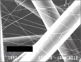
Figure 2. Nanofiber web density can be adapted and controlled. This is a low density web.
The filtration properties of nanofibers have been discussed theoretically, and a process for making them has been described. The filtration properties of nanofibers can also be shown visually by reviewing SEMs of nanofiber media that have been exposed to contamination. Figure 3 shows a cellulose media and a cellulose/nanofiber composite media (with nanofibers on the upstream side), both of which have been loaded to the same pressure drop (0.5 w.g.) with ISO Fine test dust. ISO Fine test dust is commonly used for testing engine air cleaners, and contains particles in the size range of 0.7 70 microns. The cellulose sample shows depth loading and relatively few submicron particles, while the composite sample shows loading at the nanofiber surface and a significant quantity of submicron particles captured. The composite sample is holding 2.5 times more mass of dust than the cellulose sample.
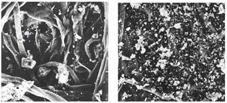
Figure 3. ISO Fine loading on conventional cellulose media (left) and nanofiber media (right).
Figure 4 shows a nanofiber composite media sample that has been exposed to a submicron sodium chloride contaminant, with particles in the size range of 0.01 to 0.5 microns. The nanofibers are covered with the salt particles, while the larger substrate fiber has collected relatively few of the submicron particles. Increased filtration efficiency for submicron contaminants can be achieved with nanofibers.
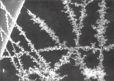
Figure 4 Sun-micron salt crystals preferentially collect on nanofibers (compared to large spun bond fiber in upper left) due to smaller fiber diameter.
Nanofiber webs have been used in a variety of air filtration applications. This section will discuss some of the unique attributes of nanofibers through an examination of their performance.
Airborne contamination in the personnel cabins of mining equipment is of concern to mining workers, mining companies and government agencies such as the Mine Safety and Health Association (MSHA). Recent work with mining equipment manufacturers and the MSHA has shown that nanofiber filter media can further reduce cabin dust concentration compared to standard (wet-laid cellulose) filter media.
Two gravimetric particle sampling devices were used on a Caterpillar 992G wheel loader, one placed just inside the cab and the other just outside the cab, both very near the cab fresh air filter. The performance of standard cellulose intake and recirculation filters were compared with composite cellulose/nanofiber intake and recirculation filters on subsequent days in August, 1998 at Kaufman North Pit in Clearfield County, Pennsylvania. A significant increase in filter efficiency was observed with the installation of the nanofiber composite filters, thus providing an improvement in worker protection (Figure 5).

For life testing, panel filters were constructed to the same dimensions as those used in the field test: 26.12 x 5.37 x 2.19, containing 186 two-inch deep pleats. Four filters were tested, two containing the standard media and two with the high efficiency nanofiber media.
SAE Fine dust was fed at a rate of 2.1 g/min to each filter element. Pressure drop data as a function of the amount of dust fed was recorded, and is presented in Figure 6. Testing was terminated when the pressure drop of the filter element exceeded 1.5 w.g. (38 mm Aq), which is the pressure drop at which mining cab filters are typically changed or cleaned. It can be seen that the increase in particle removal efficiency detailed in Figure 7 was achieved without a corresponding decrease in filter life or significant increase in initial pressure drop. Anecdotal evidence from field trials supports the data presented here.

Figure 6 Similar life with nanofiber filter and standard filter, while nanofiber filter achieves substantial efficiency increase shown in Figure 5
5. Production And Quality Control Of Nanofiber Webs
The production process and quality control of electrospinning nanofiber webs present some special challenges. The electrospinning process itself has many important technical parameters that must be understood and controlled. These include polymer and solvent selection; electrical field control; solvent evaporation and management; and nanofiber web formation and characterization.
Quality control of the nanofiber web is also important. Because of the small fibers and low basis weights, traditional on-line QC methodologies used for conventional non-wovens may not be appropriate and novel methods have been developed. A patented method has been successfully implemented to provide real-time information about web consistency in the both the machine and cross-machine direction.
ArticleSource:https://www.fibre2fashion.com/industry-article/3022/nanofiber-webs-from-electrospinning