© Copyright 2020 Foshan Membrane Technology Co., Ltd. All rights reserved. Sitemap
Solar-driven interfacial desalination (SDID) based on the local heating and interfacial evaporation is emerging to obtain fresh water with a minimized carbon foot print [1–4]. Electrospinning nanofiber membranes have been considered as an ideal supporting skeleton for water evaporation attributing to their high porosity and large permeability, which is conducive to sunlight absorption and water transport [5–7]. Superior to the evaporators of single-layer electrospinning membranes, the hydrophilic/hydrophobic double-layer structure coupled with sunlight absorption and water pumping into different layers can block the salt directly for effective desalination [8–15]. Nevertheless, considerably less attention has been paid to the combination between the hydrophilic and hydrophobic layers, which is easy to peel two layers under salty water, leading to structure failure of the Janus evaporators [16]. Besides, electrospinning membranes are intolerant to chemical and mechanical damage [17–20], preventing the devices from long-term availability and inevitably causing environment problems with the end of evaporators’ service life. Therefore, it is of great necessity and importance to solve the above-mentioned issues and simultaneously endow the evaporators with durability and sustainability.
Poly propylene glycol (PPG), 4,4-diphenylmethane diisocyanate (MDI), 2,2-bis(hydroxymethyl)propionic acid, 2,5-furandimethanol (98%+), tetrahydrofuran (THF), and hydroxyl-terminated poly dimethylsiloxanes (HDPDMS, MW 1000) were purchased from Macklin Biochemical Co., Ltd. Isophorone diisocyanate (IPDI, 99%) and N,N-dimethylformamide (DMF, AR) were supplied by Sinopharm Chemical Reagent Co., Ltd., China. Bismaleimide (BMI, 95%), NaCl, ZnSO4·7H2O, and CaCl2 were purchased from Aladdin Reagent Co., Ltd. Multi-walled CNTs (10–30 µm in length and 5–15 nm in diameter) were provided by the XFNANO (Jiangsu) Co., Ltd.
PPG (12 g, 12 mmol) was added to a glass reactor equipped with a magnetic stirrer and dried at 110 °C for 2 h under vacuum. After cooling to 80 °C, MDI (7.5 g, 30 mmol) was added dropwise to the reactor for 2 h under a nitrogen atmosphere. After cooling to 60 °C, 2,2-bis(hydroxymethyl)propionic acid (0.8049 g, 6 mmol), 2,5-furandimethanol (1.5375 g, 12 mmol), and THF (30 mL) were added and reacted for 24 h. Finally, the solution was removed under vacuum at 50 °C.
HDPDMS (12 g, 12 mmol), IPDI (5.3352 g, 24 mmol), 2,5-furandimethanol (1.5375 g, 12 mmol), and THF (15 mL) were added to a glass reactor equipped with a magnetic stirrer. Then the system was heated to 60 °C and reacted for 17 h. Finally, the solution was removed under vacuum at 50 °C.
Solutions of PPG@PU (50 wt.%) and PDMS@PU (45 wt.%) were obtained by continuously stirring the mixture of BMI (1.6 wt.% of the polymer) and DMF at room-temperature for 5 and 3 h, respectively. CNTs were dispersed in PDMS@PU/DMF solutions by ultrasonication to form dispersion with different concentrations of 0.1% to 0.5%. To fabricate PPG@PU membrane and polydimethylsiloxane based polyurethane-CNTs (PDMS@PU-CNTs) layer in Janus absorber, the resulting PPG@PU solution was electrospun for 4 h at a voltage of 12 kV, a spinning distance of 15 cm, and a feeding rate of 0.5 mL·h−1. The PDMS@PU-CNTs/DMF solution was electrospun on the as-prepared PPG@PU membrane for 2 h at a voltage of 10 kV, a spinning distance of 15 cm, and a feeding rate of 1.8 mL·h−1. The temperature was controlled at 25 ± 3 °C and the humidity was about 40% ± 5% during the electrospinning process. The Janus membrane with CNTs was assigned to “Janus-PU” while “blank sample” without CNTs. The “control sample” referred to the Janus membrane fabricated by electrospinning the PPG@PU (50 wt.%) and PDMS@PU (45 wt.%) solutions without the mixture of BMI.
The interfacial bonding of various Janus electrospinning membranes was measured using the standard 90°-peeling test (INSTRON/5969, Electronic Universal Material Testing Machine). Samples were prepared with the size of 50 mm × 15 mm. Both sides of the Janus membrane were simply adhered by VHB, while one side was attached to the plate by double-side tap to fix the sample. The resultant samples were tested with the standard 90°-peeling test with a constant peeling speed of 10 mm·min−1. When the peeling process entered steady state, the measured peeling force could reach a plateau with slight oscillations. The interfacial bonding was determined by dividing the plateau force by the width of the Janus membrane.
Strips of Janus electrospinning membrane (length × width = 20 mm × 10 mm) were prepared to test the self-healing performance. The samples were cut in the middle by a blade and then quickly aligned and fitted the fractures under the infrared (IR) lamp with 808 nm wavelength for 2 min. The single tensile tests were conducted to demonstrate the recovery of mechanical properties of the electrospinning membranes after-healing.
The PPG@PU and PDMS@PU-CNTs membranes were cut into pieces and placed separately in the sample bottle. Both of them were allowed to proceed under oven for 15 min at 120 °C; then the system was cooled to room temperature and a certain of DMF was added to prepare the spinning solution of original concentration, respectively. Then electrospinning process was carried out according to the electrospinning conditions shown in “Fabrication of Janus electrospinning membranes”. The recovery tests were repeated three times. And the samples were marked as R 1, R 2, and R 3, respectively.
Fourier transform infrared (FT-IR) spectra were taken on a FT-IR spectrometer (Perkin Elmer, Spectrum BXⅡ). Nuclear magnetic resonance (NMR) spectrum was obtained by a Bruker Avance 600 NMR spectrometer (China, avance 3 hd 600 mhz). An electronic universal testing machine recorded the mechanical properties of samples (Changchun Kexin Test Instrument Co., Ltd, WDW3020) at a tensile rate of 100 mm·min−1. Near-infrared (NIR) point light (808 nm) with output power of 582 mW was used for self-healing property measurements. Thermo-gravimetric analyses (TGA) of the PPG@PU and PDMS@PU were performed on a Discovery TGA (TA, USA) from 40–500 °C at a heating rate of 10 °C·min−1 under a N2 atmosphere. The all morphologies of PPG@PU and PDMS@PU-CNTs were characterized by Feild-Emission Scanning Electron Microscope (SEM) (China, SU8010). The water contact angles of PPG@PU and PDMS@PU electrospinning membranes were measured by an optical contact angle device (OCA15EC, Dataphysics, Germany). The whole solar spectrum absorptions (200–2,500 nm) of the Janus absorbers were measured by an ultraviolet–visible–near-infrared spectrophotometer equipped with an integrating sphere (Japan, UV3600). The ion concentrations of evaporated water were characterized by inductively coupled plasma spectroscopy (ICP-OES, USA, Prodigy-ICP).
In this study, the DA structure of furan and maleimide moieties shown in Fig. 1(a) was used to design two dynamically covalent cross-linked polymers, hydrophobic PDMS@PU and hydrophilic PPG@PU. PDMS@PU and PPG@PU were both synthesized in two steps (Figs. 1(b) and 1(e)). Two linear prepolymers were synthesized firstly (Figs. S1 and S2 in the Electronic Supplementary Material (ESM)), which then were reversible cross-linked with BMI via the DA reaction to form the dynamic cross-linked polymers. The structures of two polymers were demonstrated by FT-IR spectra in Figs. 1(c) and 1(f). Based on the dynamic nature of the DA cycloaddition of furan and maleimide moieties, it has reversible reaction processes of fast decoupling and slow binding. Specifically, the dissociation rate was much higher than recombine rate of DA reaction at high temperature. PPG@PU and PDMS@PU can maintain stable cross-linking state to ensure the stability and durability of the materials at room temperature. After heating to the DA reaction temperature, the crosslinking state of polymers immediately converted to line structure and maintained for several hours, providing a certain time window for the processing of the materials. While the dissociation rate was much lower than recombine rate of DA reaction at room temperature, the crosslinking structure was reformed after cooling, ensuring the stability of the Janus evaporator during use. The thermal stability of the polymers were also tested in Figs. 1(d) and 1(g).
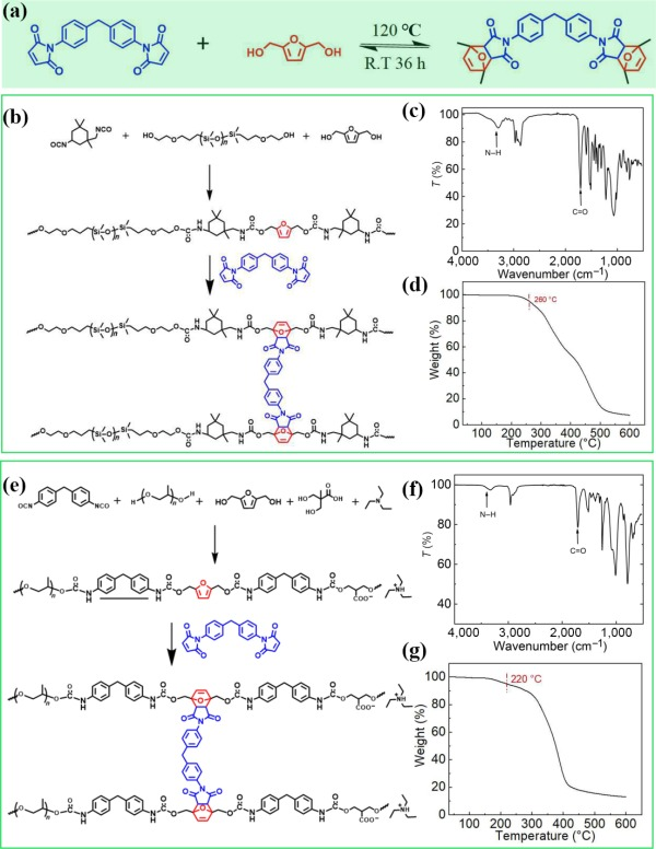
Figure 1Design and properties of the PDMS@PU and PPG@PU. (a) Molecular structure of the two polymers with dynamic covalent bond by DA reaction. ((b) and (e)) Synthesis of PDMS@PU and PPG@PU. ((c) and (f)) FT-IR spectra of the PDMS@PU and PPG@PU. ((d) and (g)) TG curves of the PDMS@PU and PPG@PU.
The Janus membrane (PPG@PU/PDMS@PU-CNTs) denoted as Janus-PU was fabricated by sequential eletrospinning of PPG@PU and PDMS@PU-CNTs shown in Figs. 2(a) and 2(c). The linear prepolymers blended with the crosslinker of BMI are dissolved in the DMF to prepare the spinning solutions and there is a processing time before the molecular chains are completely crosslinked [31]. When the electrospinning processes were finished, the as-fabricated membranes need to be placed 72 h for the polymers totally crosslinked. SEM was used to carefully examine the structures of Janus membranes. Figures 3(b) and 3(d) show the bottom and upper layer of PPG@PU/PDMS@PU-CNTs membranes, respectively, which are both comprised of a highly open microporous three-dimensional (3D) network of nanofibers, providing channels for water path and vapor escape during solar steam generation. The junctions between fibers were also formed according to Figs. 2(b2) and 2(d2). Although the two layers with different wettability (shown in Fig. 2(e)), there will be covalent bond connection at the interface due to the partly same molecular structure unit with dynamic covalent bond and crosslinking agent (Fig. S3 in the ESM), which makes the double-layer structure exist stably in the process of use. The cross-section image of the Janus membrane shown in Fig. S4 in the ESM was also confirmed that the interfaces were tightly connected without layering. And the interface bonding force was further demonstrated by the 90°-peeling test. As shown in Fig. 2(f), a part of the Janus membrane was manually peeled off to provide an initial peel arm which can be clamped by the grip of the load rig to mount a test specimen in the load rig, and a 90° peel angle is maintained throughout the test. The force–displacement curves showed that the interface bonding strength of Janus membrane was about 22 N·m−1. And there is almost no adhesion of the controlled-sample without crosslinking agent when electrospinning, while the rising curve attributed to the weight of the load cell of the mechanical testing machine. The improved interfacial bonding force guarantees the stability of the Janus structure, enabling it to long-term use.
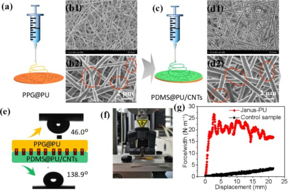
Figure 2(a) and (c) PEG@PU and PDMS@PU layer membrane fabrication by electrospinning. (b1), (b2), (d1), and (d2) The SEM morphology and the junction between the nanofibers. (e) The corresponding surface wetting property. (f) The photograph of the peeling test device. (g) Force–displacement curves registered during continuous peeling.
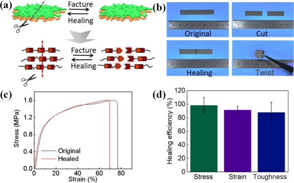
Figure 3The self-healing performance of the Janus electrospinning membrane. (a) The schematic diagram of the self-healing process. (b) Photographs of the Janus-PU membrane after being cut and healed. (c) The stress–strain curves of the pristine and the healed Janus-PU. (d) The healing efficiency of the Janus membrane.
Taking Janus-PU as a representative, the self-healing ability was examined. When the fracture surfaces were brought into close contact, reversible “fracture reaction”and “formation reaction” of reversible bonds in polymers can occur under the stimuli of external light source, resulting in dynamic structural flow and thus realizing the self-healing of the cut (Fig. 3(a)). As displayed in Fig. 3(b), a piece of the Janus-PU membrane was cut in half with a knife, and two parts were subsequently reattached closely. After placing the Janus-PU membrane under IR light of 808 nm for 2 min, the separated Janus-PU membrane was conglutinated together at the fracture, restoring its structural integrity. The Janus-PU membrane was cut and healed for three times and the membranes after healing were shown in Fig. S5 in the ESM. Tensile tests were employed to characterize the healing ability of Janus-PU membrane further. The fracture stress of the healed Janus-PU membrane recovered to 1.6 MPa (Fig. 3(c)). Accordingly, the healing efficiency of Janus-PU membrane was calculated to be 98.3%, 91.4%, and 87.8% of stress, strain, and toughness, respectively, indicating a satisfactory self-healing ability.
We designed that a simple yet efficient solar driven interfacial water evaporator could be assembled readily by adhering the Janus membranes onto a PS foam to serve as a support and an insulation layer simultaneously. And the lab setup to evaluate the vapour generation performance was illustrated in Fig. 4(a). Figure 4(b) showed the whole solar spectra absorptions of Janus-PU and blank sample, which contribute to 85% and 20%, respectively. The sunlight absorption abilities and surface temperatures with different CNTs contents were also tested, shown in Figs. S6 and S7 in the ESM. The temperature responsive time of the evaporators were also important for the evaporation performance. As shown in Fig. 4(c), it only took 200 s increasing from 20 to 54 °C for Janus-PU while 30 °C for blank sample without CNTs, proving that Janus absorber exhibited good solar-thermal conversion property. And the stable evaporation temperatures were shown in Fig. 4(d). The mass loss of devices were recorded in real-time (Fig. 4(d)), which was then used to calculate the evaporation rate of pure water under one sun. The average evaporation rate of evaporators increased with the increasing contents of CNTs from 0.6 to 1.34 kg·m−2·h−1 (Fig. 4(e) and Fig. S8 in the ESM). The results (in terms of evaporation rate and solar evaporation efficiency) were compared to the reported data of membrane evaporators on solar evaporation, as presented in Fig. S9 in the ESM. It seems that the Janus membrane in the current work is among the evaporators that have superior performance. In addition, the evaporation rate of after-healing membrane was the same as the original membrane (Fig. 4(f)), ensuring the durability of evaporators.
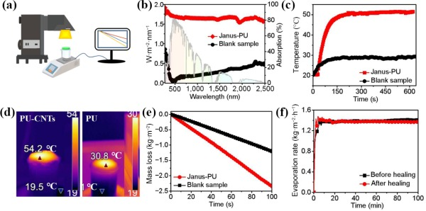
Figure 4The solar steam generation performance. (a) The setup for solar evaporation performance measurement. (b) The absorption spectra of the Janus evaporators of Janus-PU and blank sample (right hand side axis), and solar spectral irradiance (left hand side axis) weighted by standard AM 1.5G solar spectrum. (c) Temperature response time curves of Janus-PU and blank sample under 1 sun. (d) The surface temperature when evaporating under one sun illumination. (e) The mass loss curves of pure water under one sun. (f) The evaporation rate of Janus-PU before- and after-healing.
As illustrated in the Fig. 5(a), for Janus evaporator, the solar-driven vapor generates at the hydrophilic/hydrophobic interface, where the salt is blocked directly and redissolved into the bulk water owing to continuous water pumping. We monitored the photothermal performance of Janus-PU for up to 12 h under one sun illumination (Fig. 5(b)), the evaporation rate was almost invariable in the whole process. And there is no salt accumulation in the hydrophilic layer (seen in Fig. 5(c)). The cycle performance of the evaporator is shown in Fig. 5(d). As the evaporation performance can reach a steady state after 1 h, the whole solar desalination tests were sustained for 1 h each day over 10 days to verify that Janus-PU evaporators could carry out stable evaporation process for a long time. The steady-state evaporation rates under different illumination intensity are shown in Fig. 5(e), the evaporation rate is 1.34 kg·m−2·h−1 under 1 sun, 2.45 kg·m−2·h−1 under 2 sun, 3.52 kg·m−2·h−1 under 3 sun, and 4.84 kg·m−2·h−1 under 4 sun, respectively. We also simulated sea water (3.5 wt.%) for solar desalination, and the concentrations of four main ions in seawater (Na+, Mg2+, Ca2+, and K+) were tested in Fig. 5(f). All the concentrations significantly decreased far below than the values defined by World Health Organization (WHO) after evaporation, confirming that the Janus device can offer an effective clean water production technology.
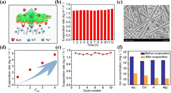
Figure 5The desalination performance of the Janus-PU evaporator. (a) The schematic illustration for desalination of Janus evaporator. (b) The evaporation rate of the Janus evaporators using 3.5% NaCl solution for 12 h. (c) The SEM of the PPG@PU layer after long-term evaporation. (d) The solar steam generation under different illumination intensity. (e) The cycle number tests under 1 sun illumination of 3.5% NaCl solution. (f) The measured concentration of the four simulated seawater samples before and after desalination.
The Janus evaporator exhibited fully reconfigurable property shown in Fig. 6(a). When PDMS@PU-CNTs and PPG@PU membranes pieces were heated at 120 °C (DA reaction temperature) for 15 min respectively, the covalent cross-linking network in the material temporarily disappears. DA addition structure re-dissociated into furan and maleimide units by retro-Diels–Alder (rDA) reaction at high temperature, giving them easy reconfiguration ability. The materials show the properties of linear thermoplastic material and can be dissolved in DMF and other organic solvents at room temperature after stirring for 10 min (Figs. S10(b) and S10(d) in the ESM). While, they were not able to dissolve in the DMF (Figs. S10(c) and S10(f) in the ESM) at room temperature owing to the covalent cross-linking structure. The reconfiguration experiments were repeated three times and the photothermal performance after recycling was also tested in Fig. 6(b). The performance of evaporators recovered by dissolution is basically consistent with that of the original evaporator with the evaporate rate of ~ 1.32 kg·m−2·h−1. This synthetic materials may have more advantages in the field of solar interfacial seawater desalination than previously reported materials. In real-word application, strong light, chemical oxidation from exposure to highly oxidative chemical and organic solvent in water, etc. often result in failure of the evaporators. As a result, the materials with cross-linked structure which can not only stably exist at room temperature but also be dissolved and re-processing after heat treatment, the reconfiguration ability, would be a judicious solution to lead to elongated use of these materials.
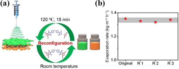
Figure 6Schematic diagram of (a) recovery and reconfiguration process and (b) water evaporation performance.
We developed two dynamic materials of PPG@PU and PDMS@PU based on reversible DA bond and electrospun into double-layer structure for solar steam generation. The combination force between the interface of the Janus evaporator was greatly improved by the covalent bonding according to the similar molecular structure design of two polymers. Besides, the integrated evaporator was endowed with self-healing properties by the DA reaction, which the mechanical properties and photothermal properties were maintained before- and after-healing. The Janus evaporator can achieve a stable evaporation rate of 1.34 kg·m−2·h−1 during 5 h without the salt accumulation in 3.5 wt.% NaCl solution. In addition, the whole device can be reconfigured, while the evaporation rate of the evaporator was almost the same. The new material and design principles will inspire a series of next-generation solar-steam seawater desalination evaporators.
Supplementary material (NMR spectra, molecular structure formula, IR images, the full solar absorption spectra, the figures of evaporation rates, the optical photograph of reconfiguration, and self-healing tests) is available in the online version of this article at https://doi.org/10.1007/s12274-022-4733-4.
Show Author's information : Huijie Liu, Jiatai Gu, Ye Liu, Lei Yang, Liming Wang( ![]() ), Jianyong Yu, Xiaohong Qin1(
), Jianyong Yu, Xiaohong Qin1( ![]() )
)
1Key Laboratory of Textile Science & Technology of Ministry of Education, College of Textiles, Donghua University, Shanghai 201620, China
2State Key Laboratory for Modification of Chemical Fibers and Polymer Materials, International Joint Laboratory for Advanced Fiber and Low-dimension Materials, College of Materials Science and Engineering, Donghua University, Shanghai 201620, China